OK, with a week to go i thought id better take stock and write up what needs doing before then, and a wish list of jobs. This update is more for reference for me, so a bit of a boring one. :)
So here goes. Before the week off, so this week:
1. Polish Top Arm, LDP and Centre vent surround plate.
2. Wire the 5v supply via the switch (to follow) to the 4 body Arduinos. Maybe use space on servo shield as a power bus.
3. Wire top charge USB input to the slip-ring.
4. Wire bottom charge USB input to the input for the battery.
5. Wire CBI output USB charge direct to 1A output of battery.
6. Wire 12v for 5v converter to the Rigrunner.
7. Reconnect wiring for the actuators.
8. Dig out all my clamps and clips, and maybe grab another load. :)
Then during the week I hope to attempt to get the best part of this lot done or started:
1. Strip skins.
2. Roll rear skins flat. I dropped it, not the right shape any longer. :(
3. Refit and JB Weld the JAG hinges into place on body and doors.
4. Glue up door trims. Not looking forward to this, tried before and it didn't last.
5. Glue up rear door, hinges and magnets, may have to polish the door on the real R2 that is normally alu. Yet to decide. :)
6. Attach arm carrier to skins.
7. Attach inner skins to skin snaps.
8. Refit and glue in the power couplers, octo ports and coin slots.
9. Attach all doors and fit servo rods, test all servos on the body and find open/close points.
10. Attach Outer skins. Either VHB or JB weld, leaning towards VHB.
11. Attach all missing panels and coin returns.
12. Remount the centre vents to correct position and attach surround (method to follow :) )
13. Polish backs of pocket and Side vents and refit.
14. Debug pad problem. James' is fine, mine isn't letting me turn off the dome, has to be wiring or XBee set-up.
15. Rewrite pad start up to include the R1+Triangle then Triangle magic combo to stop the pad crashing. Like an unlock code. :)
16. Mount switch/button for 5v battery feed.
17. Add correct command numbers to servo code and add required scripts.
18. Retest Audio, dome drive, dome position, feet drive, dome lights and servo set-up with body servos and CBI.
19. Rejig 2-3-2 set-up and test as just the frame. Mainly actuator alignment. Then Redo actuator points for 2-3-2 action.
20. Redo master and 2-3-2 controller code to add feet drive during 2-3-2 and add 2 leg mode sense and driving mode.
21. Add an extra combo scrip or two, James has had a great idea for one, watch this space :) Also add a few of the fun audio options as their own commands. :)
22.? Look at the 5v battery and see if the on off switch can be rewired to be more accessible.
So actually its wire and polish everything up. Then sort the skins and test everything so far. Then sort the 2-3-2. But really, if i get the skins on i will be happy enough. Rather get it right than rush it. :) So the list and the order may evolve, but doesnt hurt to think ahead. :)

Monday 25 February 2013
Sunday 24 February 2013
Body Servos and Volume Knob
A good weekend, not the most productive, but progress. :)
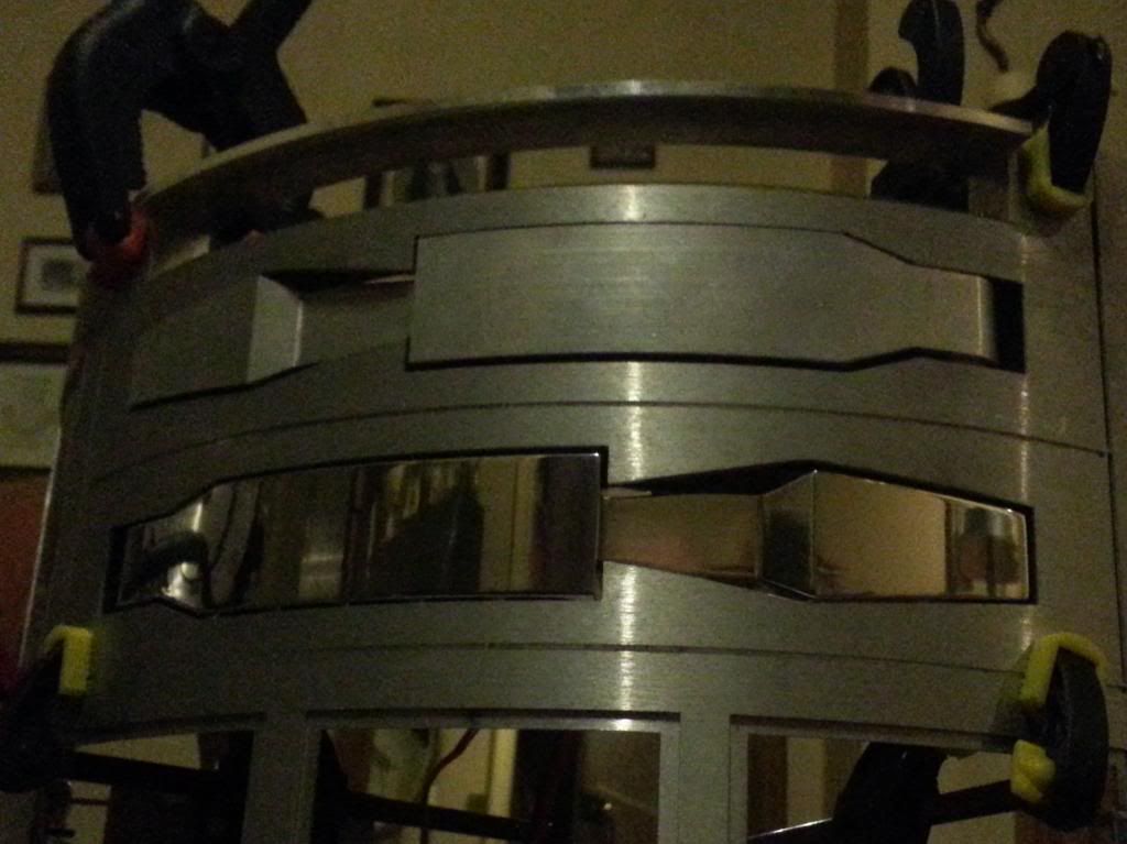
Over the last week I have been polishing up one of the utility arms. Its finally done, after about 5 hours of sanding and polishing, lots of slight machine marks to sand out took ages.
I mounted the 5 door servos using 15x2mm flat bar as a bracket, with 2 M3 screws and nylocks. Even did the 2 outer ones without having to strip the whole frame. :) Then i wired them all up to the shield extending where needed.
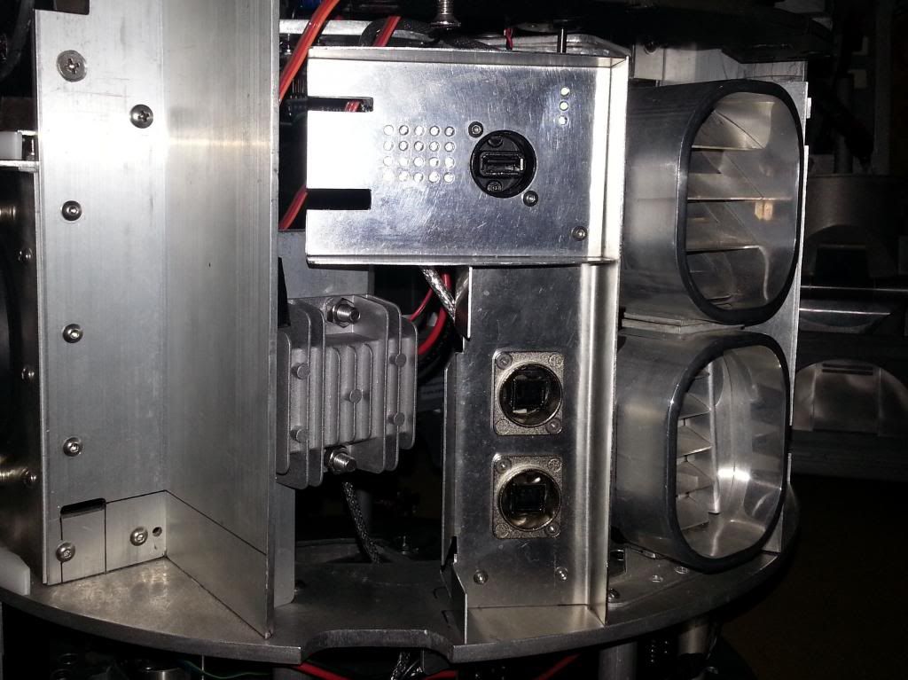
Then I remounted and rewired the MP3 Arduino and started work on the volume knob. It was a painted alu, so I got out my polishing stuff and buffed it up. Looks much better. The LEDs should work too, just off board replacements. :) I may end up flipping the volume PCB, but that means trimming the bracket, so maybe later. :)


I have decided to add a button to switch off the power from the body's 5v supply, this will go in the same door. I will still need to turn the battery on from the button on the pack, but off would be easier with a button than unplugging the battery. So USB to in and out of battery, and one to the slip ring for the dome battery charge, then the other body battery USB will go to the button then on to the 3 Arduino it has 2.1A output, so fingers crossed it can cope.
So wait for the button, do the 5v power set-up reinstall the 2-3-2 set-up and I'm ready to work on the skins. Then once those are done servo rods and a feck load of testing and coding to get everything back on-line and working reliably and i will be almost ready for the NEC. :)
Over the last week I have been polishing up one of the utility arms. Its finally done, after about 5 hours of sanding and polishing, lots of slight machine marks to sand out took ages.
I still have the top one, The LDP and the centre vent surround to go, but just couldn't face any more sanding. So I pressed on with the body set-up.
I mounted the 5 door servos using 15x2mm flat bar as a bracket, with 2 M3 screws and nylocks. Even did the 2 outer ones without having to strip the whole frame. :) Then i wired them all up to the shield extending where needed.
Then I remounted and rewired the MP3 Arduino and started work on the volume knob. It was a painted alu, so I got out my polishing stuff and buffed it up. Looks much better. The LEDs should work too, just off board replacements. :) I may end up flipping the volume PCB, but that means trimming the bracket, so maybe later. :)
I have decided to add a button to switch off the power from the body's 5v supply, this will go in the same door. I will still need to turn the battery on from the button on the pack, but off would be easier with a button than unplugging the battery. So USB to in and out of battery, and one to the slip ring for the dome battery charge, then the other body battery USB will go to the button then on to the 3 Arduino it has 2.1A output, so fingers crossed it can cope.
So wait for the button, do the 5v power set-up reinstall the 2-3-2 set-up and I'm ready to work on the skins. Then once those are done servo rods and a feck load of testing and coding to get everything back on-line and working reliably and i will be almost ready for the NEC. :)
Sunday 17 February 2013
Body Servo Shield and 5v Supply
Busy weekend here, R2 is stripped to pieces and I have several jobs on the go. :)
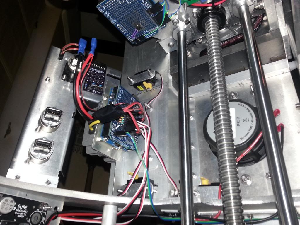
Having sorted most of the code, I started to look at mounting everything it needed. I was forced to remove the volume knob and the MP3 Arduino. Then I mounted the 50W 12v-5v DC converter on a bracket and mounted the body Arduino to the back. It sits in the hole left by the coin slots.
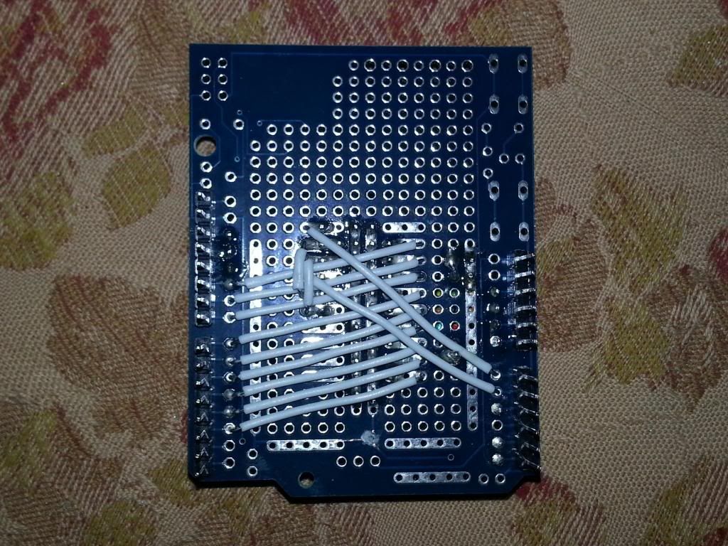
I sorted the shield, it has all the connectors for the CBI, including power, all 11 servos are wired up (may have to rethink if I use higher power ones for the arm and claw), the voltage divider with 12v input from the converter supply, and power in via Vin pin. I am going to redo the wiring for the 5v servo power with 3x 2 way heavy duty servo leads, I don think the current ones will take the load, but an easy upgrade.


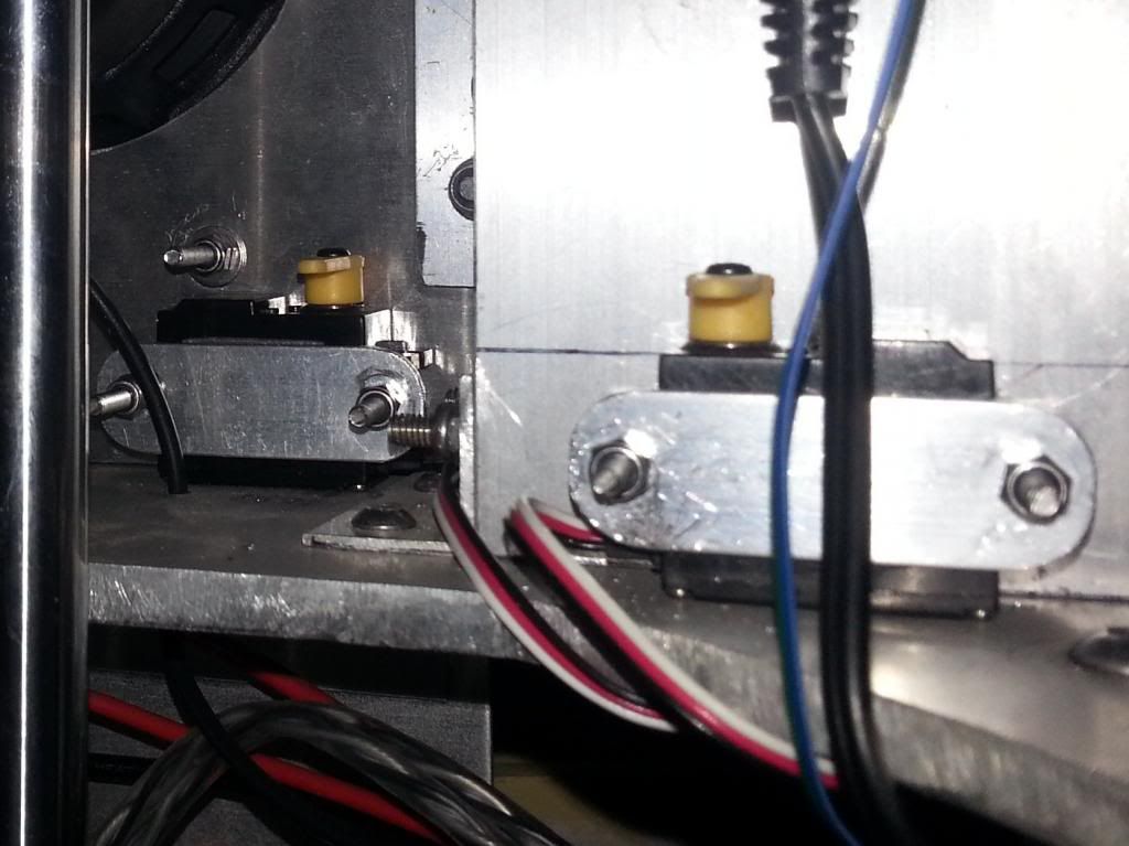
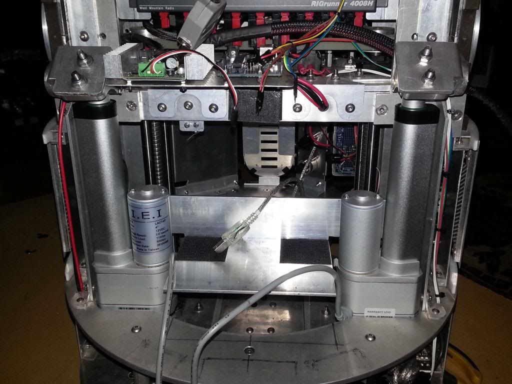
I also got the actuators back in, really tight on the mounts, but one of my mountings wasn't quite square, so it has to be pulled over to meet the arm, that actuator is then really firm, but not sure if it will cause me problems, so may need to loosen a few bolts and see if I can get it to sit right. The one that sits perfectly still has a bit of play, but only from the actuator, the mounts are perfect. I think when fitted correctly the 2 actuators will have a similar amount of play, maybe about 1mm.
After looking at the volume knob and trying to figure out a location, I spotted it had holes for header pins to allow the use of remote LEDs, so I am going to mount the knob in the big central door at the bottom and mount the LEDs with it. :) If it works :) So that and remount the MP3 Arduino don't you just love this shuffling lark, luckily those bits were only half mounted anyway, so at least they will find a home soon.
So I need those extra servos, servo rods and the extension leads I ordered and I can crack on. Also ordered some Scotchbrite pads in 2 flavours to help polish up the arms, fingers crossed they help. :) I am looking good to be ready for skins in 2 weeks time. :)
Also I hope to get a Raspberry Pi tomorrow, may not use it in R2 just yet, but will be fun to have a play with. :)
Having sorted most of the code, I started to look at mounting everything it needed. I was forced to remove the volume knob and the MP3 Arduino. Then I mounted the 50W 12v-5v DC converter on a bracket and mounted the body Arduino to the back. It sits in the hole left by the coin slots.
I sorted the shield, it has all the connectors for the CBI, including power, all 11 servos are wired up (may have to rethink if I use higher power ones for the arm and claw), the voltage divider with 12v input from the converter supply, and power in via Vin pin. I am going to redo the wiring for the 5v servo power with 3x 2 way heavy duty servo leads, I don think the current ones will take the load, but an easy upgrade.
I also got the actuators back in, really tight on the mounts, but one of my mountings wasn't quite square, so it has to be pulled over to meet the arm, that actuator is then really firm, but not sure if it will cause me problems, so may need to loosen a few bolts and see if I can get it to sit right. The one that sits perfectly still has a bit of play, but only from the actuator, the mounts are perfect. I think when fitted correctly the 2 actuators will have a similar amount of play, maybe about 1mm.
After looking at the volume knob and trying to figure out a location, I spotted it had holes for header pins to allow the use of remote LEDs, so I am going to mount the knob in the big central door at the bottom and mount the LEDs with it. :) If it works :) So that and remount the MP3 Arduino don't you just love this shuffling lark, luckily those bits were only half mounted anyway, so at least they will find a home soon.
So I need those extra servos, servo rods and the extension leads I ordered and I can crack on. Also ordered some Scotchbrite pads in 2 flavours to help polish up the arms, fingers crossed they help. :) I am looking good to be ready for skins in 2 weeks time. :)
Also I hope to get a Raspberry Pi tomorrow, may not use it in R2 just yet, but will be fun to have a play with. :)
Wednesday 13 February 2013
Voltage Divider for CBI
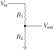
Last night was fun. I
started by playing with resistors and making the required voltage divider for
the CBI Arduino. I used R1 as 47K and R2
as 23.7K (measured using meter). Then
made sure I was getting a 0-5v signal from it.
Once that was hooked up I read the analogue pin (A2) to see the fluctuation
in readings, with the conversion to the 0-15v range the output result was
fluctuating quite a lot. So I did 2
things:
1. Read the pin 4 times and took an average of the 0-1024 value given
by the pin.
2. Calculated the 0-1024 value of the min and max voltages based on
the up to 15v battery voltage, this saves the calculation having to be done on
every read.
It is really fast and smooth, and the accuracy is actually very
good, within +/- 0.05v.
So with that done I converted it into a function to generate the
0-20 (number of LEDs to show), it simply translates the measured voltage within
the min/max range and then maps that to a 0-20 value, but as the readings and range are in the 0-1024 format, there is no further calculation required other than the mapping. Then I retested the divider base code and all
looked good. Then I added it into the
main CBI code and it worked like a charm.
Just need to find the max voltage for my battery (all above will show as full), and the
empty voltage that will show as no LEDs and it will be ready to use.
I hooked it up to a couple of SLAs to test it worked and it worked fine, I
was trying to work out the voltage from the number of LEDs, I even edited the
code to get a reading on 1 battery that was outside the range I had set, turned
out that when read with a meter it was 7.2v!
So the end result is code that I add the min and max voltages as
the battery levels e.g. 11.8v and 13.7v, and the resistances e.g. 47000 or 23700 ohms as variables and the rest is done in
the code. Really pleased. Will try and add one of these to the Teeces
kit too, then I can use my bar graph option to show the charge level on the
logics, the 12v is passed via the slip ring so can be measured in the dome too.
So CBI and Body servo code is ready for the droid now, last thing to do in the code is to choose the buttons to use to trigger stuff. Mount those servos this weekend, and get it installed.
Sunday 10 February 2013
Actuator Refinements and More Code
James is coming in handy once more. He very kindly took my actuators and brackets and offered to take out the slop, there was at least a mm play over the 2 brackets on each,so that related to a pretty big slop in the leg position, its the last bit to tweak that I wasn't happy with. I hope that these, redoing the positioning on the actuators, a bit of a timing tweak on the leg lift and adding feet drive to the motion so that the centre foot doesn't move will make it a really stable 2-3-2. It was a lot more stable when the feet could roll, and if I can simulate that it would be great and take out the caster twist that causes issues as it pushes the centre leg forward. This is what he came up with, Silver steel shaft, brass collar fixed on one end that goes into the head hole in one side of the bracket, and a split pin hole on the other end. Spot on. Cant wait to get these back in and test a few theories. :)


Looks perfect, Thanks James Has to be loads better than me with a hand drill. :)
The CBI code is still progressing at pace. I have 7 servos in the code now, 2 Utility arms, and 5 doors. The CBI only flashes when that door is open and is put into the sleep state to save power when the door is closed. I have all the I2C stuff in too to trigger the servos and the lights. Just need to choose the buttons to use and apply the script numbers, oh and fit the 5 door servos. :) Looks like I might need to move the MP3 Arduino, so more unexpected work. But I did trim that amp bracket and finally bolt in the Big pan, it fits nicely now. Skins are getting closer. :) Should be close to being ready for the week off. But need to get polishing soon too. I don't want to have to strip the arms once fitted to the skins. :)
Friday 8 February 2013
CBI Progress
Progress is good on the CBI, without the row/column confusion of the Teeces this is simple. I have messed about and added a few scripted options and refined my random a little. Then I moved on to the idea of using it to display charge level, no voltage divider yet, or any idea of voltage levels, but just the mechanics of displaying the LEDs. I input a value of 0-20, and that number is counted out on the display, the 3 side ones are also broken down to show charge level into 4 lots of 5 with 0-5 being all 3 LEDs off. Works well. :)
So that is the LED bit ready, Triggering next, then Servos. Decided to make life easy and start the random mode when door is opened, then loop one random each main loop, that way I can still trigger other body stuff while random runs, but if I trigger a CBI script, i have to wait for that to finish before being able to do other stuff on that Arduino If I keep the CBI scripts short it should be fine. :)
So that is the LED bit ready, Triggering next, then Servos. Decided to make life easy and start the random mode when door is opened, then loop one random each main loop, that way I can still trigger other body stuff while random runs, but if I trigger a CBI script, i have to wait for that to finish before being able to do other stuff on that Arduino If I keep the CBI scripts short it should be fine. :)
Thursday 7 February 2013
CBI Works and Basic Random Code
James popped in tonight, the plan was to get some of the CBI and body servo code written. So we wired up the remaining LEDs (well James did), and we hooked it up. Nothing. :( The chip was dead, once we found a good one it worked perfectly.
Unfortunately it did cost us most of the night getting it running, but we did get a simple random mode sorted with a random level for the 3 level LEDs:
I like it, good enough for this job.
I will add a few more scripted modes, would like to do the battery meter here too and do a percentage on the 20 main LEDs on demand, as well as the constant 3 level LEDs, but not sure how it would work or if it would be remotely accurate, but worth a go. :) Then add the I2C triggering and servo control that will work while the CBI scripts are running, sort the servos and get it all working installed. :) Fingers crossed.
Subscribe to:
Posts (Atom)